


Types of Wind Turbines
8 min read
Horizontal-Axis Wind Turbine
Video: 3D model of a horizontal-axis wind turbine.
Free Downloads › Animations / 3D model of a horizontal axis wind turbine
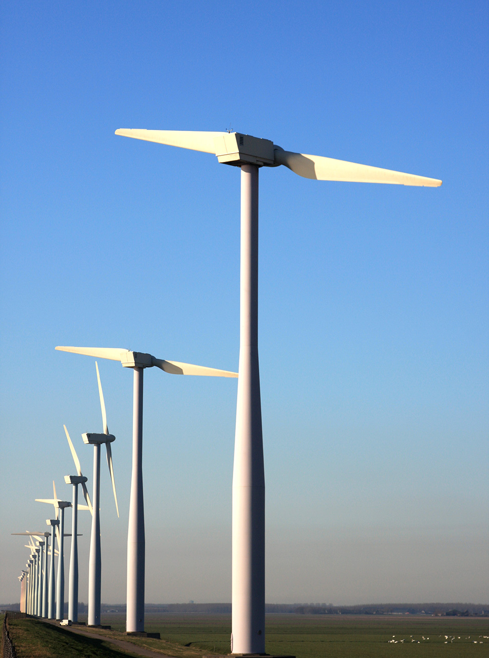
This is the most common type of wind turbine. The blades are designed to generate lift as air flows around their aerodynamic profiles. Modern large wind turbines can have rotor diameters exceeding 200 metres and typically achieve maximum power coefficients of around 45—50%.
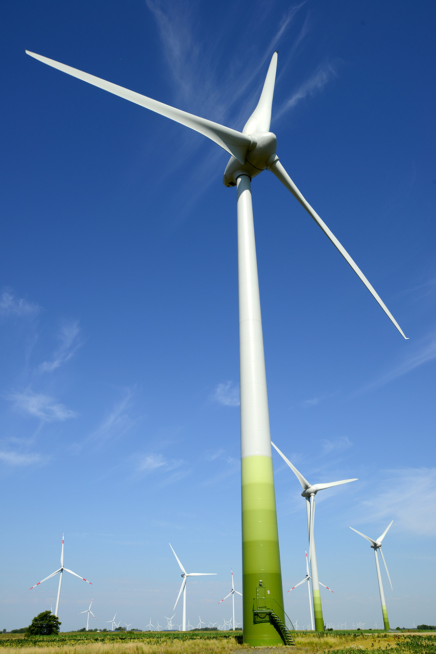
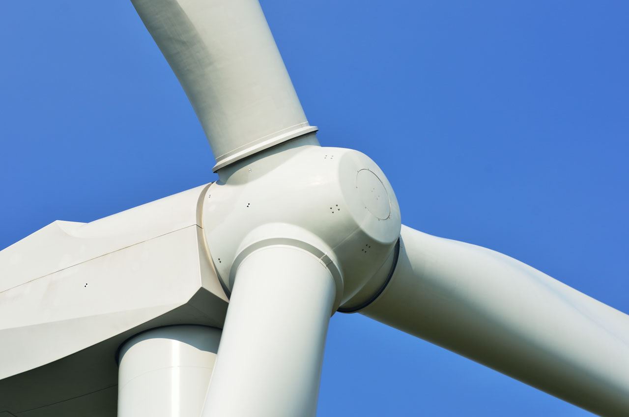
Horizontal-axis wind turbines constitute the majority of commercially produced installations. Their main parts include a rotor, usually with three blades, a main shaft and an electric generator; depending on the design, a gearbox may also be used. The drivetrain is housed in a nacelle mounted on top of a steel or reinforced-concrete tower. Small turbines may use a wind vane to keep the rotor facing the wind. Larger turbines use an electrically controlled yaw system to turn the nacelle according to signals from wind direction sensors. Most horizontal-axis turbines have the rotor on the upwind side of the tower to avoid aerodynamic disturbance caused by the tower. Downwind rotors can align more readily with the wind, but their blades repeatedly pass through the turbulent wake behind the tower, increasing cyclic loading and fatigue. Today, most horizontal-axis wind turbines use an upwind rotor.
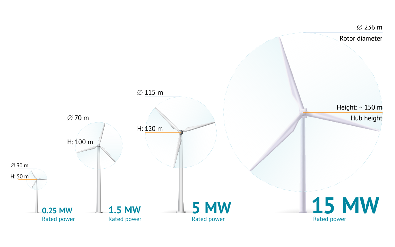
The growth of wind turbine size and rated power.
Free Downloads › Images / The growth of wind turbine size and rated power
Online 3D Model / Wind Turbine
Free Downloads › Online 3D / Wind Turbine
The tip speed ratio of modern horizontal-axis turbines can be around 6 or higher. This means that at a wind speed of 50 km/h, the blade tips may move at about 300 km/h. With blades 40 metres long, such a rotor would revolve approximately 20 times per minute. In conventional geared turbines, this rotational speed is increased by a gearbox to drive a higher-speed generator. Other wind turbines use a multipole generator connected directly to the main shaft and therefore do not require a gearbox.
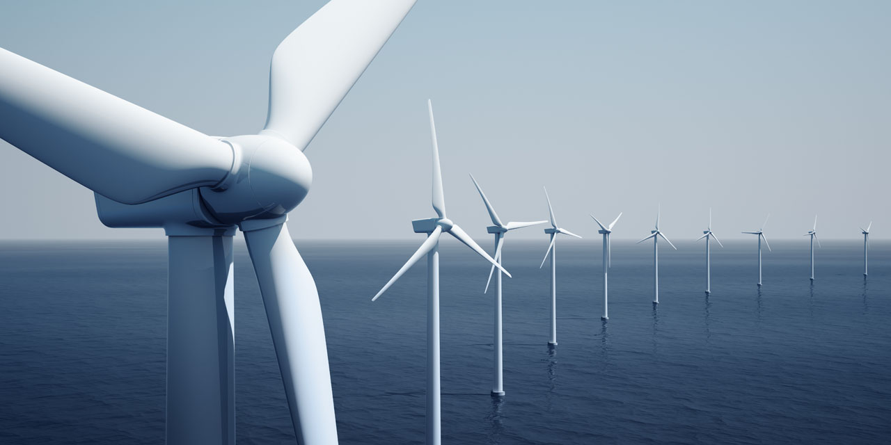
Modern horizontal-axis wind turbines typically have rated outputs of several megawatts, with the largest offshore turbines reaching considerably higher capacities. For large-scale electricity generation, multiple turbines are grouped into wind farms. The typical design lifetime of a modern wind turbine is around 20—25 years.
14 pictures
14 pictures
Manufactured blades are matched according to their weight, weight distribution and natural frequency so that the blades fitted to one rotor have similar properties.
The blades of the largest wind turbines now exceed 100 metres in length, presenting a major challenge for transportation. One solution is to manufacture blades in several sections that can be transported separately and assembled on site. Enercon was one of the pioneers of this approach, using two-part blades on its large turbines.
Tubular steel wind turbine towers are constructed from rolled and welded steel plates. Depending on the tower design and the loads involved, plate thicknesses can range from around 12 mm to 40—50 mm and may reach about 70 mm in particularly demanding designs.
Vertical Darrieus Wind Turbine
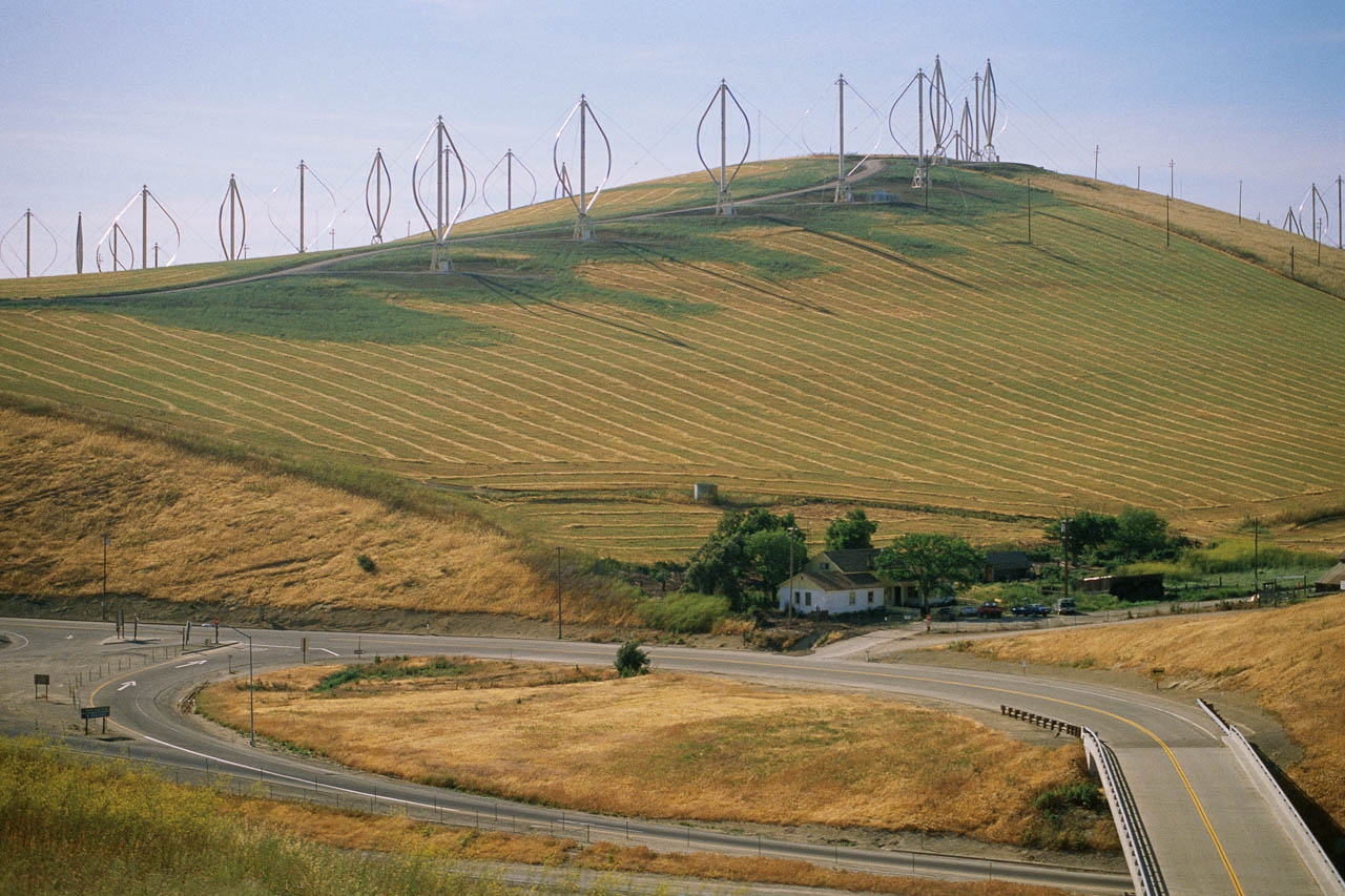
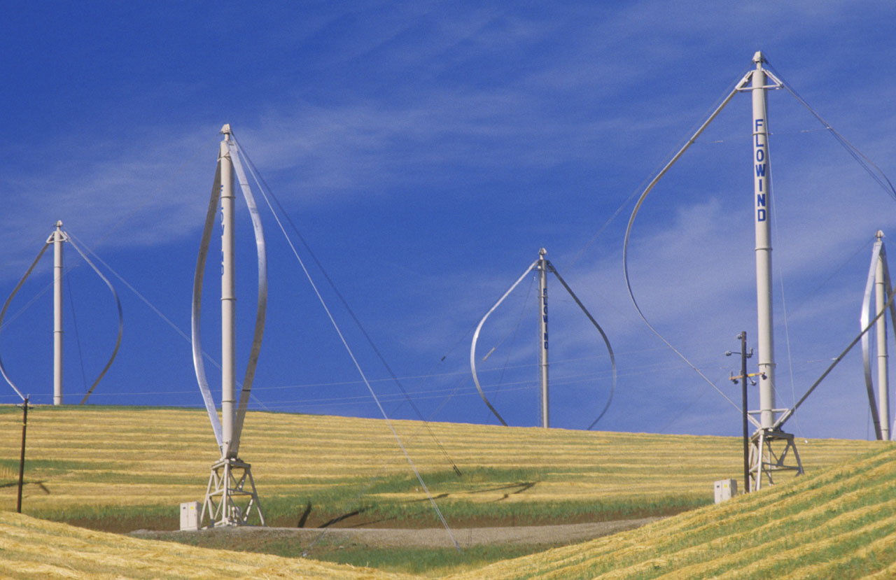
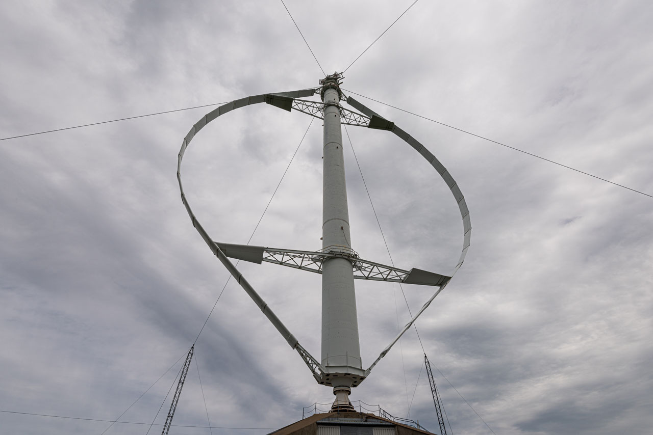
This vertical-axis turbine was invented by the French engineer Georges Jean Marie Darrieus. The turbine usually consists of two or three aerofoil blades that rotate around a vertical axis, forming a cylindrical, spherical or parabolic swept surface. Since blade speeds can be several times higher than the wind speed, Darrieus turbines are classified as high-speed wind turbines. This imposes high requirements on the blades and their mountings because of the considerable centrifugal forces involved.
Darrieus turbines can operate with wind from any horizontal direction and can achieve power coefficients of around 35—40%. They extract energy mainly through lift. As an aerofoil blade rotates around the vertical axis, the direction of its motion relative to the wind continuously changes. As a result, the relative airflow and the angle of attack also change throughout each rotation. The resulting angle of attack produces lift on the aerofoil. A tangential component of this aerodynamic force produces torque around the rotor axis and causes the turbine to rotate.
One variant of the Darrieus turbine has an H-shaped rotor. It is easier to manufacture because the aerofoils are straight, but their mountings must withstand considerable centrifugal forces. To reduce torque pulsations, some Darrieus turbines use helical blades, which distribute the aerodynamic loading more evenly during rotation.
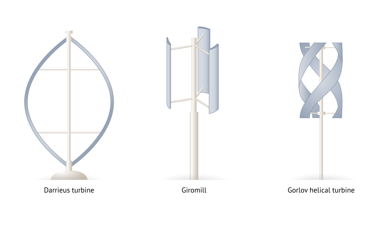
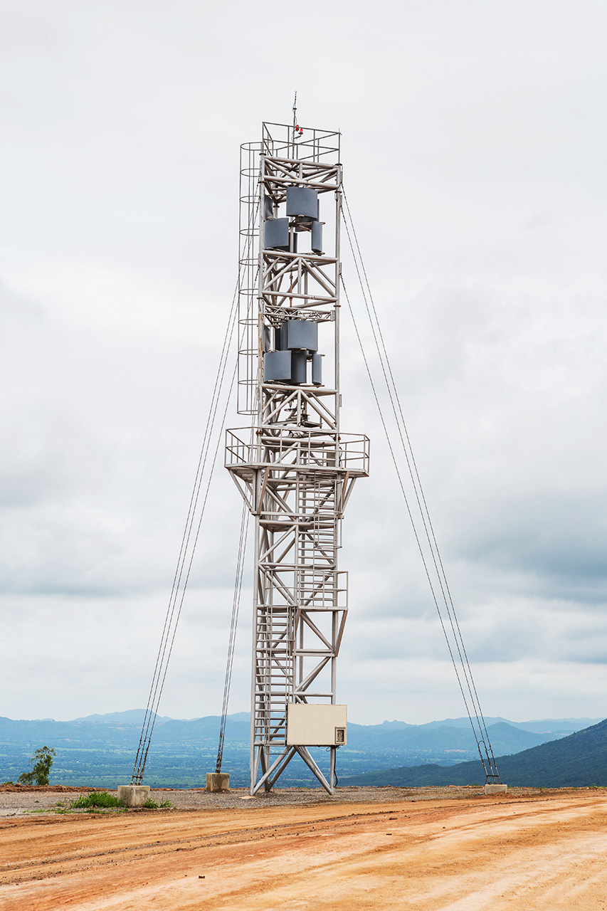
Different designs of Darrieus-type wind turbines.
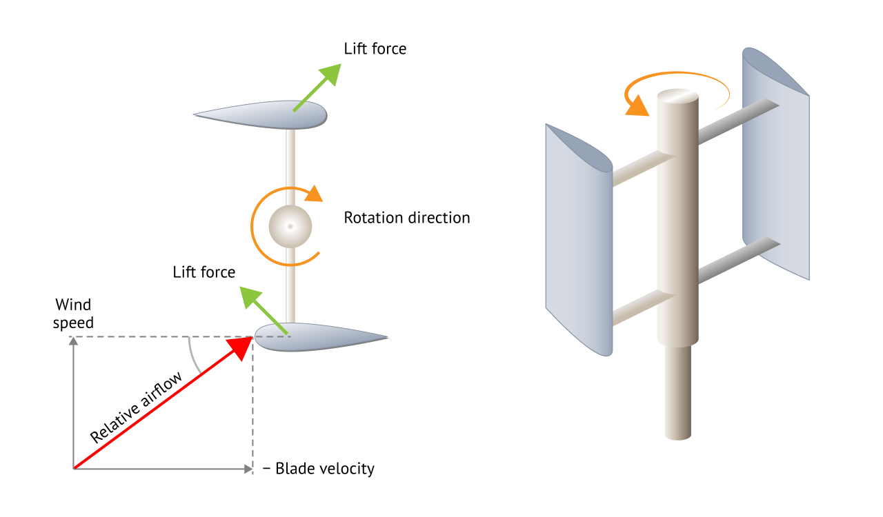
The working principle of a Darrieus turbine.
Free Downloads › Images / The working principle of a Darrieus turbine
Advantages of Darrieus turbines include their ability to operate independently of wind direction and the possibility of locating major drivetrain components near ground level. On the other hand, many Darrieus designs are not self-starting and require assistance to begin rotating. Other disadvantages can include torque pulsations, difficult control and high cyclic and centrifugal loads on the rotor. These cyclic loads can impose significant fatigue stresses on Darrieus turbine components and must therefore be taken into account in their design.
8 pictures
8 pictures
Vertical Savonius Wind Turbine
Video: 3D model of a Savonius turbine.
The Savonius turbine is one of the simplest wind turbine designs. It was developed by the Finnish engineer Sigurd J. Savonius in 1922. The turbine extracts energy mainly through drag and belongs to the category of low-speed wind turbines, with a tip speed ratio generally below 1. Its maximum power coefficient is typically around 20%.
The turbine consists of two curved, approximately half-cylindrical blades attached to a vertical axis, forming a shape similar to the letter S when viewed from above. The difference in drag between the concave and convex sides of the blades produces a net torque that turns the rotor. The axis of rotation is perpendicular to the wind direction. The inner edges of the blades usually overlap, allowing some air to pass between them. The Savonius rotor turns relatively slowly but produces high starting torque. These characteristics make it suitable for applications such as pumping water and other low-speed mechanical drives. Savonius turbines can also be used for small-scale electricity generation, although their relatively low power coefficient limits their use for larger installations.
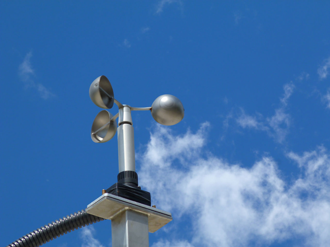
A disadvantage of a simple two-bladed Savonius rotor is that its starting torque can be very low at certain rotor positions. This can be reduced by using helical blades or several rotor stages mounted at different angular positions on the same shaft. Some wind-speed measuring instruments also use rotors based on a similar drag principle.
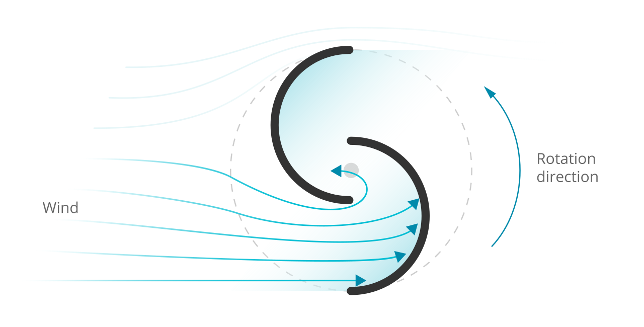
The working principle of a Savonius turbine.
Free Downloads › Images / The working principle of a Savonius turbine
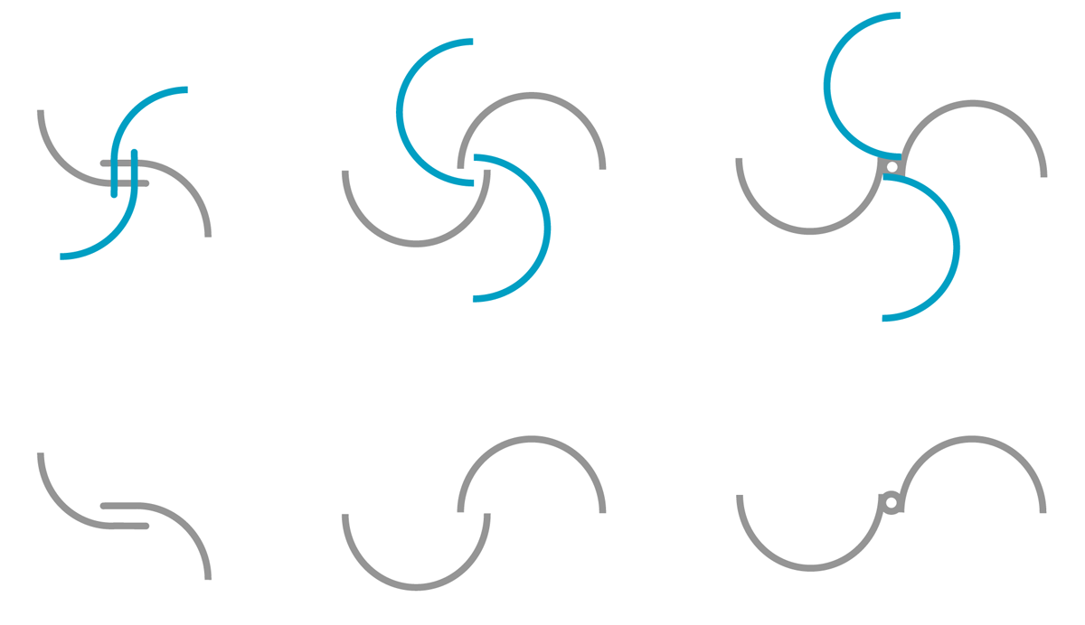
Different configurations of a Savonius turbine rotor.
6 pictures
6 pictures
Wind Turbine Efficiency Graph
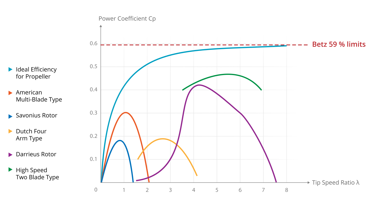
The tip speed ratio λ (lambda) is the ratio of the circumferential speed of the blade tips to the wind speed.


Robie, your AI assistant